FUEL PUMP

- The pump is basically a jerk type with a plunger moving in a matched barrel, using two helical grooves machined in the plunger to control the end of injection by uncovering spill ports and causing the discharge pressure to drop rapidly, thus causing the needle valve in the injector to close.Oil is supplied to the barrel via the spill ports and a suction valve. The suction valve, situated at the top of the barrel opens when the pressure in the barrel falls below the supply pump pressure; i.e. during downward stroke of plunger, while spill ports are covered by plunger.
- Replaceable erosion plugs are fitted in the pump housing opposite the spill ports. The high pressure oil, spilling back, as the edge of the helix uncovers the spill ports at the end of injection, hit the plugs, which prevent damage to the pump casing
- No relief valve is provided as it is connected to the suction chamber thru helix at the delivery. Double helix is provided to avoid side thrust. Secondary injection is prevented by having no delivery valve.
- Suction valve helps for recirculation and prevents cavitation and secondary injection. Suction valve was of plate type before and is Slide type now.
- A puncture valve is fitted in the top cover of the pump. It is opened when compressed air from the control air system acts on top of a piston fitted in the top cover. Fuel oil from the discharge side is then returned to the suction side of the pump and no injection takes place. The puncture valve is operated in the event of actuation of the shut down system (all units), during the air start sequence or when excessive leakage is detected from the double skinned fuel pipes.
- Fuel oil leakage past the plunger to the cam case is prevented by the use of an "umbrella" seal".

- The fuel inj char are to great extent controlled by the fuel cam flank design in which the angle of dwell plays no role in injection. The cam is designed to give high rate of acceleration initially and later is more or less constant.
- The angle of dwell is provided to strengthen the nose of the cam and match with the fuel cam reversing angle, exh vv reversing angle and the starting air distributor, so that a common reversing servo can turn the shaf. The cam dwell is 330degrees but is not termed as negative cam in MAN B&W. Follower is at top for 330degrees and comes to BDC for only 30degrees. The dwell has been shaped to reduce the angular shift reqd while reversing.
VARIABLE INJECTION TIMING
The reason for using VIT is to achieve greater fuel economy and reduce sfoc. This is achieved by advancing the injection timing so that maximum combustion pressure (pmax) is achieved at about 85% MCR (maximum continuous rating).
The system is set up so that there is no change in injection timing at low loads (40% MCR). This is to avoid frequent changes of pump lead during manoeuvring.
As the engine load is increased above 40%, the start of injection advances. When the engine has reached approximately 85% MCR at which the engine is designed to have reached pmax, the servos retard the injection timing so that the maximum combustion pressure is kept constant between 85% and 100%MCR.
At 90% MCR a fuel saving of 4-5g/h.p.hour is claimed to be achieved.
Variable Injection timing also allows for small adjustments to the fuel pump timing to be made to allow for fuels of varying ignition qualities. Wear on the fuel pumps can also be compensated for as can changes in the camshaft timing due to chain elongation (up to 2 degrees)

Fuel pumps are designed to meter the fuel quantity and end of the injectin based on the load. They are designed to achieve Pmax at 100% MCR.
Conventinal VIT used in GB and L35/42 MC, has a fixed barrel and special profile in the plunger. The fuel pump index has a fixed relationship with the injection timing. Thus, pump index cannot be varied without varying the injection timing.
VIT makes use of a sleeve threaded to the barrel so that the spill port can be varied to change the start of injection. VIT moves the barrel and fuel index moves the vertical helical distance of the plunger from the spill port. VIT servo cylinder receives control air signal from the governor and FQS(Fuel Quality setting ) lever.
The pilot valve is pre adjusted to achieve a fixed break point, at which the Pmax has been achieved and the fuel injection has been advanced to maximum. Above the breakpoint the injection timing is gradually retarded back until it reaches its original setting at 100% MCR load. The position of the breakpoint is determined by the layout of the engine. Formerly it was generally considered to be at approximately 85% MCR load, but it also has to be ensured that the maximum pressure rise from compression to maximum cylinder pressure is 35 bar or less (recommended by MAN B&W Diesel A/S). For this reason the breakpoint has tended to be somewhat higher on the latest engines (approximately 90% MCR load).
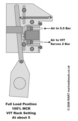
Low pressure air (5.5bar) is fed to the pressure control valve. The pilot valve has been preadjusted to vary its output from 0.5-3.5bar for a movement of 0.5-8mm its pin.A link from the governor output (or fuel pump control handwheel) moves a pivoted bar, the position of which determines the output of the pressure control valve. The output control air is fed to the VIT servos on the fuel pump, which moves the VIT rack correspondingly.
The position of the control valve is adjustable which can be used to allow for fuels of varying ignition qualities and changes in the camshaft timing due to chain elongation.
The pivots are also adjustable for initial setting up of the VIT and adjustment of breakpoint position.


SUPER VIT
Super VIT can be both mechanical and electrical system. The advantage of the electronic version is that the break-point is calculated from the actual conditions, why the ambient conditions are taken into account. The engine load is calculated from the engine speed and the fuel index, while the compression pressure is calculated from the scavenging air pressure. Based on these calculations the governor calculates the output to the I/P converter.
An electronic governor gives an electrical signal (4-20mA) to I/P convertor of each fuel pump which generates 0.5-5bar of equivalent pressure to change the VIT rack. The electronic governor considers the scavenge pressure and accordingly varies the break point. This is important parameter because if the sc pr is high, its corresponding compr pr will be high, and unless its comb is adjusted, Pmax could go high beyond the designed pressure. This is achieved by changing the break point to a lower % of the MCR and then maintained constant.

The electronic control is only active when running ahead when the engine is in bridge control or ECR control. When running astern or in local engine side control, the manoeuvring system delivers a preset pressure to the VIT actuators. Adjustments during running are simpler, as correction values are entered directly into the governor. Change in fuel quality or wear in the fuel pumps may make it necessary to adjust the VIT.
ADJUSTMENT OF VIT
VIT adjustment varies Pmax of the cylinder.

ADJUSTMENT OF VIT
VIT adjustment varies Pmax of the cylinder.
1. Individual cylinders can be done by displacing the VIT rack. Increasing the rack increases the comb pr & viceversa. One index of VIT changes Pmax by 3-4 bar.
2. Adjustment for the all units is done if the fuel pumps worn or camshaft timing has changed due to chain elongation.In a Mechanical VIT, the axial movement of the bracket with the pilot valve wrt the lever. To increase the Pmax, move towards the lever and viceversa
3. Adjustment for the all units in Electronic system is by changing the P-offset value in the Governor panel, ECR. One gradutaion mark of P-offset changes the combustion pressure by 1bar. Later check the indicator diagram after the breakpoint to ascertain the adj. Also check if the pressure gauge reading after the I/P convertor is in accordance with the curve.
COMMON RAIL SYSTEM
The following are the advantages of the common rail system:
1) Same injection pressure for the engine at all loads or rpm which is not possible in jerk pumps as the later is dependent on the engine speed.
2) Injection timing can be varied during running of the engine, whereas in conventional system the engine has to be stopped and setting for timing has to be changed.
3) The design of common rail is simple as there are no individual fuel pumps and cams for each fuel pump are also removed.
4) The common rail gives smokeless operation whereas in conventional system smokeless operation is only during high rpm.
5) Reduced maintenance is required because of less number of pumps and increased efficient combustion time between overhauls.
6) With this system control of variable opening of exhaust valve can also be done which is not there in traditional system.
Fuel pressure independent of engine speed and load conditions. This allows for flexibility in controlling both the fuel injection quantity and injection timing and enables better spray penetration and mixing even at low engine speeds and loads. This feature differentiates the common rail system from other injection systems, where injection pressure increases with engine speed. This characteristic also allows engines to produce higher torque at low engine speed—especially if a variable geometry turbocharger (VGT) is used. It should be noted that while common rail systems could operate with maximum rail pressure held constant over a wide range of engine speeds and loads, this is rarely done. As is discussed elsewhere, fuel pressure in common rail systems can be controlled as a function of engine speed and load to optimize emissions and performance while ensuring engine durability is not compromised.
2. Lower fuel pump peak torque requirements. As high speed direct injection (HSDI) engines developed, more of the energy to mix the air with fuel came from the fuel spray momentum as opposed to the swirl mechanisms employed in older, IDI combustion systems. Only high pressure fuel injection systems were able to provide the mixing energy and good spray preparation needed for low PM and HC emissions. To generate the energy required to inject the fuel in approximately 1 millisecond, the conventional distributor pump would have to provide nearly 1 kW of hydraulic power in four (in a 4-cylinder engine) 1 ms bursts per pump revolution, thus placing considerable strain on the drive shaft [Breitbach 2002]. One of the reasons behind the trend toward common rail systems was to minimize the maximum pump torque requirement. While the power and average torque requirements of the common rail pump were similar, high pressure fuel delivery is to an accumulator and thus the peak flow rate (and peak torque required to drive the pump) does not have to coincide with the injection event as is the case with the distributor pump. Pump discharge flow can be spread out over a longer portion of the engine cycle to keep pump torque demand more even.
3. Improved noise quality. DI engines are characterized by higher peak combustion pressures and, thus, by higher noise than IDI engines. It was found that improved noise and low NOx emissions were best achieved by introducing pilot injection(s). This was most easily realized in the common rail system, which was capable of stable deliveries of small pilot fuel quantities over the entire load/speed range of the engine.
Working of Common Rail System
The common rail system consists of a high pressure pump which can be cam driven or electrical driven or both. Pressure requirement will be different for different system. For fuel oil the pressure are as high as 1000 bars, for servo and control oil the pressure is about 200 bars.
The common rail system consists of a high pressure pump which can be cam driven or electrical driven or both. Pressure requirement will be different for different system. For fuel oil the pressure are as high as 1000 bars, for servo and control oil the pressure is about 200 bars.
The high pressure pumps are driven by camshaft with three lobe cams. These pumps makes several stroke with the help of three lobe cams and speed increasing speed gear.
Fuel pump design is based on a jerk type pump with a control groove whose position is changed by a rack. Plungers are turned axially by 200bar l.o. pressure. The fuel pump develops 1000bar pressure and is given to common rail through an accumulator. It waits in the INJECTION CONTROL VALVE till it is opened.
The control unit consists of 2 electrical driven pumps which supplies l.o. at 200bar pressure through an accumulator to the control rail.
A RAIL CONTROL VALVE is provided for each INJECTION CONTROL VALVE per unit.
WARTSILLA ELECTRONIC CONTROL SYSTEM sends a signal to RCV to time the fuel start and end of injection based on the crank angle encoder.
When RCV gets energized, it will allow the hydr oil to pass to ICV, the pressurized fuel oil is injected.
The fuel vv pressure and the pressure behind the F.O. QUANTITY PISTON maintains the pressure at injectors.
As the desired qty is injected, which is known from the fuel qty piston feed back signal, computer deenergises the RCV solenoid.
ICV will interrupt the fuel supply and thus the fuel qty piston comes back to normal position.
FUEL TIMING
When plunger is resting in bottom, the distance of the suction port above the top of the plunger determines the start of injection. In this position, the tally marks on plunger and housing should coincide, which is checked usually by a window cut in the housing.
ZERO SETTING means, the fuel plunger helix should be inline with the spill port so that there is no injection. This is ensured while assembling the rack in the sleeve of the plunger. One gear of the sleeve is slightly cut which should go in between the two cut gears of the rack, which ensures zero setting.
ADJUSTMENT
Adding one shim gives early injection and increases Pmax by 1bar.
Changing 1degree of camshaft position relative to crankshaft changes Pmax by 3bar.
In M/E, Pmax is adjusted by varying VIT index and MIP is varied by fuel index arm.
The indidual Pmax should not deviate more than 3bar from the avg value of the cylinders.
The MIP should not deviate more than 0.5bar from the avg of all cylinders.
FUEL PUMP LEAD

FUEL CAM LEAD
When plunger is resting in bottom, the distance of the suction port above the top of the plunger determines the start of injection. In this position, the tally marks on plunger and housing should coincide, which is checked usually by a window cut in the housing.
ZERO SETTING means, the fuel plunger helix should be inline with the spill port so that there is no injection. This is ensured while assembling the rack in the sleeve of the plunger. One gear of the sleeve is slightly cut which should go in between the two cut gears of the rack, which ensures zero setting.
ADJUSTMENT
Adding one shim gives early injection and increases Pmax by 1bar.
Changing 1degree of camshaft position relative to crankshaft changes Pmax by 3bar.
In M/E, Pmax is adjusted by varying VIT index and MIP is varied by fuel index arm.
The indidual Pmax should not deviate more than 3bar from the avg value of the cylinders.
The MIP should not deviate more than 0.5bar from the avg of all cylinders.
FUEL PUMP LEAD
Fuel pump lead is the distance in mm, the top of the plunger lifts above the upper edge of the upper cut-off holes in the barrel, when the relevant unit's piston is at TDC.
The special tool has a constant D1 (80mm for MAN B&W S50MC), which is calculated at the point where the plunger passes the upper edge of the upper cut-off holes at zero VIT index.
Procedure to check the pump lead
1. The concerned unit to be at TDC.
2. Shut the fuel inlet vv to the concerned pump and drain
3. Remove the pin from the forked lever of VIT rack and pull it to zero setting.
4. Remove the puncture valve and place the tool on the top cover
5. Push the pin down into the threaded portion of the plunger
Fuel pump lead is adjusted by using shims or by changing vit rack. The fuel pump lead changes if camshaft timing is changed.

FUEL CAM LEAD
"the no of mm the plunger is lifted from its bottom position when the main piston is at TDC.
- lift the punture vv
- Turn the engine until the lowest point of the cam is found, using a caliper. Push down the measuring pin through the top cover, until it rests against the plunger
- measure the distance from the top of the measuring pin to the transverse piece. This is X2
- Turn until the main piston is at TDC. Measure the distance as X1.
- (X1-X2) gives the cam lead.
Cam lead is adjusted by moving the cam position relative to camshaft using an impact spanner. The ducts on cam shud b connected with a snap on coupling using 3 copper gaskets. Pressurise using hydr pp and wait for 5mims before moving the cam position. After ajusting... Check with smaller pin gauge and remove the pressure. Wait for 15mins for the cam to settle.

CAUSE OF CAM DAMAGE

CAUSE OF CAM DAMAGE
Nozzle spray holes choked which gives a back pressure
Delivery vv of fuel pp leaking which exerts shock wave once the fuel vv closes
FUNCTION OF DELIVERY VALVE
- Separate hydraulically pump from the high pr pipe
- Smooth the pr wave running back once the inj vv snap closes (1300m/sec). this shock wave is transmitted back to cam thru the pump and pitting occurs on cam.
- Maintain certain pr in the high pr pipe for next injection stroke
FUNCTION of SPCV
Thank you for sharing your information with us.i will follow all rule at my project. I hope that you will share more knowledge with us in future.
ReplyDeleteFuel Pump
very good sir,the article clarified that this pump does not have delivery valve unlike bosch jerk type pump.i did not understand the concept of secondary injection,the reason for absence of delivery valve.
ReplyDeletethanks
SSRakan
Thanks for sharing the post.. parents are worlds best person in each lives of individual..they need or must succeed to sustain needs of the family. fuel system cleaning
ReplyDeleteThanks for a wonderful share. Your article has proved your hard work and experience you have got in this field. Brilliant .i love it reading. centralina aggiuntiva chippower
ReplyDeleteThank you so much for sharing about High Pressure Plugs. Keep sharing it.
ReplyDeleteI enjoy your style of writing. I’m wondering in the event you might take a short look at my article and let me know what you think regarding my style. I am not a natural English speaker and so this is why I ask. centralina aggiuntiva bosch
ReplyDeleteIs this pump for sulzer rtflex 96c engines?
ReplyDeleteExcellent and very exciting site. Love to watch. Keep Rocking. mustang brake calipers painted
ReplyDeleteTop 10 Logistics Companies in India TCI express is a flourishing express delivery solution. For a memorable delivery experience to their customers, TCI express considers ensuring a secure delivery solution.
ReplyDeleteMe and my team was in search of a rarely found platform which can help us for our new assignment. We are writers and its been a long time we are in this writing field. So we would appreciate help of this blog. Gasket For Fmf Cap Handrail
ReplyDelete;Continental Controls Corporation is an ISO 9001 Certified Company that delivers the most trustworthy quality flow meter & gas Totalizer for reliable and economical gas flow measurement - if you want fuel measurement on individual turbines and gas engines.
ReplyDeletePipe umbrella system KSA
ReplyDeleteCanopy Tubes KSA
ReplyDeletewow such an interesting blog. It is very informative
ReplyDeleteTruck repair service New Jersey
TCIEXPRESS is a name that stands out when it comes to effective and trustworthy logistics services. Tci Express Businesses looking for smooth logistics solutions now turn to tci express because of its dedication to providing quality and a strong focus on customer satisfaction.
ReplyDeleteLeading provider of trustworthy and efficient logistics services is TCIEXPRESS Tci Express Because of its commitment to quality and emphasis on customer satisfaction, businesses now look to TCI Express for efficient logistical solutions
ReplyDeleteI really loved reading your blog. I also found your posts very interesting. Fuel Oil Supplier Pennsylvania
ReplyDeleteThis blog does a fantastic job of explaining the main engine fuel pump and its VIT system, breaking down complex technical details into easy-to-understand information. It's an excellent resource for anyone in the maritime field who wants to deepen their understanding of engine mechanics. The clarity and structure make it a useful read. On a different note, having similarly detailed guidance is essential when navigating processes like Selling Used Car Brisbane, ensuring everything goes smoothly.
ReplyDeleteThe detailed explanation of the main engine fuel pump and VIT is both informative and well-presented. Understanding these intricate systems is crucial for anyone involved in marine engineering. For those in Castle Hills, opting for services like Cash for Scrap Cars Castle Hills ensures that old vehicles are responsibly handled, reflecting a commitment to both efficiency and environmental care.
ReplyDeleteThe detailed breakdown of the main engine fuel pump and VIT is very informative. Just as maintaining these systems is vital for optimal performance, it is equally important to manage the disposal of old vehicles efficiently. In Sydney, services like Cash for Kia cars Sydney offer a practical solution for responsibly handling vehicle disposal.
ReplyDeleteThe explanation of the main engine fuel pump and VIT is very informative, highlighting the importance of maintenance for efficiency. Similarly, if you're looking to upgrade or sell your vehicle, you can Sell my car for cash in Sydney to get value from it easily.
ReplyDeleteEngines are the core of every vehicle. yanmar diesel engines
ReplyDeleteNice Blog. Thanks for sharing with us. Such amazing information. Dyed diesel
ReplyDeleteExceptionally detailed and informative breakdown of the main engine fuel pump and VIT system! Clear explanations on plunger motion, valve function, and spill port mechanics. This post is as efficient and reliable as a VPS hosting server under peak load — structured, consistent, and built for performance. Great job!
ReplyDeleteGreat post! Cracks in concrete can lead to serious structural issues if not addressed early. I recently searched for concrete crack repair near me and found a local team that did an excellent job sealing the cracks and preventing further damage. It's definitely worth investing in professional repair before the problem worsens. Thanks for raising awareness about this important maintenance step!
ReplyDeleteSpot on about the bump to babypram pram! Such an important piece of gear. My top tip: check the fold size if you have a small car boot!
ReplyDeleteDiesel is trusted for big machines. 350 mercruiser
ReplyDeleteTrusted lifting solutions with certified cranes. industrial lifting equipment
ReplyDeleteSo keeping the page loading speed fast, may in the future help with the all important Google ranking.aviation parts marketplace
ReplyDeleteMobile autoglass repair technician explained everything clearly. Car window replacement Addison
ReplyDeleteEfficient marine engines help reduce emissions. yanmar sd60 saildrive price
ReplyDeleteGreat article! An oil recirculation system is essential for maintaining consistent lubrication and cooling in industrial machinery. By continuously filtering and recirculating oil, it helps reduce component wear, improve efficiency, and extend equipment life. Very informative content.
ReplyDeleteAt SMM Panel One, we are passionate about helping businesses and digital creators navigate the ever-changing world of social media marketing. Our platform is designed to support effective online growth through practical social media solutions that promote visibility, engagement, and audience development. By combining simplicity, reliability, and a customer-focused approach, SMM Panel One aims to make social media management more accessible for brands of all sizes seeking sustainable digital success.
ReplyDeleteVisit- https://smmpanelone.com/