CRITICAL TEMP is the temp above which the vapor cannot be condensed by isothermal compression
CRITICAL PRESSURE is the lowest pr at which a gas can exist in liquid state at its critical temp
REFRIGERATING CAPACITY rate at which a sys will absorb heat from the space.
Tonne of refrigeration(Battu) Is the rate of heat removal reqd to freeze a metric tonne of water at 0C in 24hrs.
Net Refrigeration Effect is"the quantity of heat that each pound of refrigerant absorbs from the refrigerated space to produce useful cooling"
1. Refrigerant properties @ enthalpy(Battu)
Evaporator - liq refrigerant must hav low boiling point to avoid the necessity of high vacuum;
- high latent heat of vaporization to reduce qty of refrigerant n reduces m/c sizes n speeds.
Then as a gas - low specific vol in vapor state to reduce the size;
- must have high critical temp so that s.w. at its highest temp can condense ref
- low condensing pr. to avoid heavy compressor
Non-corr, non-toxic, non-flammable & non-explosive.
Cheap, easily stored and easily available;
Chemically stable under working cond and environmental friendly
no reaction with oil i.e., oil must be miscible
2. SAFETIES IN REF SYSTEM
· Cyl head vv assembly lifts in case water is drawn in. this is provided cos the vv lifts so small abt 2mm that a relief vv is not useful.
· High pressure or HP cut out: As the name suggests, the high pressure cut out activates and trips the compressor when the discharge side pressure increases above the limit value. The HP cut out is not auto reset and has to be done manually. The reason behind it is to manually attend the fault which is leading to rise in pressure, else this situation can lead to overloading of compressor parts and may damage the same
· Low Pressure or LP cut off: This is a compressor safety which cut off the compressor in the event of pressure drop in the suction line. The pressure of the suction line is continuously sensed by the control unit and when it goes below the set value, which means the room is properly cooled, the LP cut out will auto trip the compressor. When the pressure rises, indicating there is flow of refrigerant in the line due to increase in room temperature, the LP switch will start the compressor.

- Oil differential cut out: This safety is again for compressor as it is the only machinery in the circuit having rotational parts which requires continuous lubrication. In the event of low supply or no supply of lube oil to the bearing, the differential pressure will increase and activates a trip signal to safeguard the bearing and crankshaft.
- Relief valves: Relief valves are fitted in discharge side of compressor and will lift and safeguard the compressor in the event of over pressure. One relief valve is also fitted in the condenser refrigerant line to avoid damage to the condenser if there is high pressure in the discharge line.
- Solenoid valves: Master solenoid valve is fitted in the common or main line after the condenser discharge. It closes when compressor stops or trips to avoid over flow of refrigerant in to evaporator. All holds or rooms are fitted with individual solenoid valve which control the flow of refrigerant to that room.
- Oil heater: Oil heater is provided for the compressor crank case oil and prevents compressor from getting excessively cold which may effect the lubrication of the parts
3. Refr filling
Can be done by vapour filling (red) to the suction side of the compressor
Or can be done by liq filling (blue vv) to a charging connection fitted btw condenser o/l and desicant filter or directly to the filter.
Following steps are to be taken for charging gas into the reefer plant:
1. Connect gas bottle or charging cylinder, vacuum pump and charging point in the reefer system to the valve block.
2. The discharge of the vacuum pump is to be connected in the empty recovery bottle
3. First open the valve between vacuum pump and charging bottle located in the valve block without opening the main valve of the charging cylinder. This will remove all the air inside the pipe. Once vacuum is reached, close the valve of charge cylinder in the valve block
4. Now open the valve of the charging point pipe in the valve block and run the vacuum pump until the vacuum is reached. This will remove the trapped air from this pipe. Then shut the valve in the valve block
5. Now keep the system idle for 5 minutes to check there is no pressure drop. This will ensure there are no leakages in the system
6. Now open charging bottle pipe valve and the charging point pipe valve located in the valve block. This will set the line for charging. Ensure that the vacuum pump valve is shut
7. Now open the main valves in the charging cylinder and charging point of the reefer system
8. Do not overfill the system. Make sure the receiver has 5 % space for expansion
Ensure that no refrigerant is leaked out in the environment as these effects the ozone layer in the atmosphere.
Note* :Gas bottle is kept on weighing scale for measuring the amount of charged supplied to the system.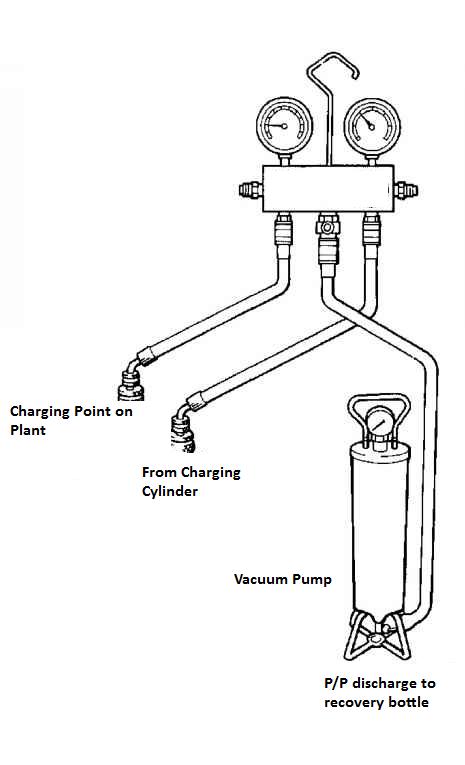
4. CAPACITY Control
Capacity control of a refrigeration plant can be defined as a system which controls the output of the plant as per the load in demand. As the load (temperature) of one room is achieved, there will be no more need of the refrigerant for cooling. Hence, the solenoid valve supplying refrigerant to that room will shut. This functionality is called capacity control.
The refrigeration compressor consists of different units working in parallel to cope up with the load. As the load decreases, the capacity control system cut off one or more units (depending upon the load) and maintains the efficiency of the plant by reducing stresses on different parts.
Components and Working of Capacity control system
1. Compressor lube oil pump supply
2. Capacity control valve
3. Capacity control regulating valve
4. Un-loader assembly
The compressor lube oil pump supplies oil to all the bearings and one connection is provided to the capacity control valve.
The capacity control valve is provided with high pressure oil from the compressor lube oil supply pump. This valve has several grooves bored in to its periphery and connected to the un-loader mechanism of different units.
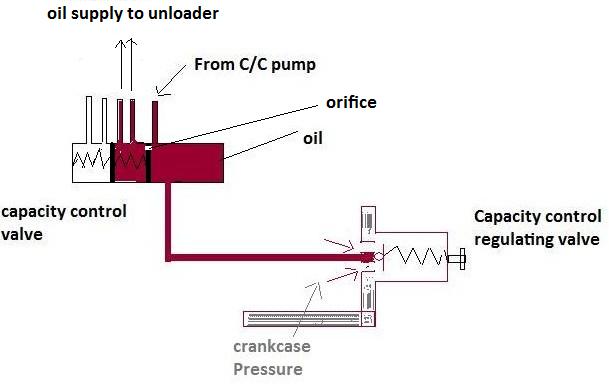
A spring piston is provided which controls the spreading of high pressure oil supply in to the bore chamber. The spring piston is pressed by the oil supplied through an orifice which pushes the piston and aligns the un-loader holes, supplying high pressure oil to the un-loader unit.
The un-loader assembly co mprises of a un-loader piston held by a spring. The un-loader piston is connected to a rotating cam ring having lifting pins attached to th suction valve. The lifting pins always act on the suction valve i.e. un-loading the unit at stop condition.
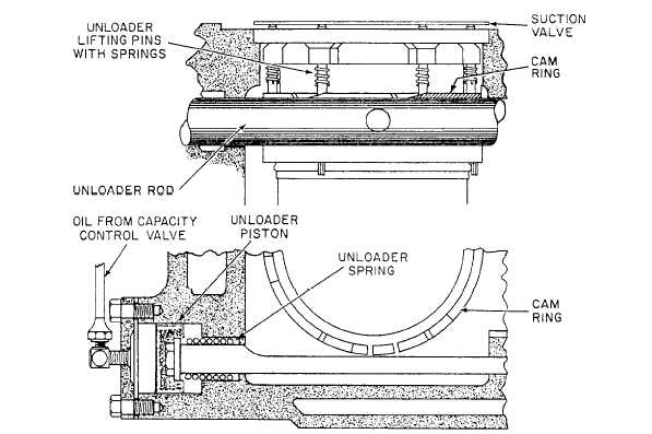
When the bores on control valve aligns with the un loader bores, oil will pass and press the un-loader piston rotating the cam and releasing the un loader pins from the suction valve.
The capacity control regulating valve is responsible to control the pressure (opening and closing of capacity control valve ports with un-loader ports). Its one end is connected to the crankcase and other end to capacity control valve.
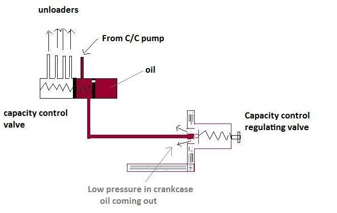
As the pressure in the crankcase drops due to reduction in load, oil in capacity control valve is drained into the crank case leading to closing of un-loader ports, lifting of the suction valve, and cutting of the cylinder unit.
5. Properties of ref compr oil
Low pour point -42
Low floc point
High flash point
High viscosity index means less visc changes for temp changes
Miscibility to refrigerant and can be easily separated
No reaction with sys materials like gaskets and seals
No water absorption
6. OIL FILLING
I method --- using a separate oil pump without affecting the operation of the compressor forcing the oil into the c/case against suction pr
II method…. Close the suction vv slowly to drop the suction pr below atm pr and with the charging vv open, the liquid is drawn in.
III method - stopping
7. Only meat room temp.high reason(Battu)
8. AC giving air with high humidity wat will u do(Battu)
HEATING BY STEAM COIL/heater in separate cabins
SINGLE DUCT by way of sensing the humidity from the return duct of the AHU, cooling further to condense the water and the heating by hot water humidification or steam injection to increase
TWIN DUCT
9. Solenoid valve of meat room burnt(…….B)
10. what is secondary refrigerant and why and wher used
mainly for the incompressible liquid being drawn into the compressor thru the suction line
11. using same refrigerant , wht is d differece b/w COP of refer compressor and AC comp-ressor.(Battu) a/c compresses ambient temp say 35 deg , ref max7 or 8 deg---reeds---266
Coefficient of Performance is Heat extracted by the refrigenat to the heat equivalent of the work done under compression.
COP of AC = 1+COP of REF
The COP of the refrigerator and air-conditioner can be less than one or greater than one. The above formula also shows that the COP of the heat pump can never be less than one; it is always more than one.
It is worth mentioning here that efficiency of the engine can never be more than one, but the COP of the heat pump is always more than one. You should know that the terms efficiency and the COP are entirely different terms. The efficiency describes the capacity of the engine to produce power from the fuel, while the COP indicates how effectively the energy is used to produce the desired effect which is producing heat in case of the heat pump and coolness in case of the refrigerator.
A.C COMPRESSOR WILL HAVE HIGH COP THAN REFER COMPRESSOR, FROM GRAPH, MOLIER CHART (REFER VINOD BOOK)
12. Hot gas defrosting(…..)hot gas defrosting.. Where is defrost pipe connection given..
(Battu)
(Battu)
13. Refer compressor fitted with cylinder head lift arrangement, no relief valve, reason(Battu)
14. Why evaporator outlet led to reefer compressor crankcase?
To prevent liquid hammer
assist in oil cooling.
Since crankcase is pressurized, air cannot enter
Even if blowpast is der, no loss of refrigerant
15. Purpose of back pressure v/v after veg room(Battu) Function of back pressure valve in ref sys.(Sinha) 
16. Air Comp & AC comp unloader function(Bhowmick)
WHERE AS IN AC, UNLOAD ONLY AT THE START, AND THAT TO LIFT SUCTION V/V AT START


17. AHU in air conditioning system full description. (Bhowmick)
18. Expansion vv pr. before and after which is more and why .how cooling takes place after expansion...meat room and veg room temp. Very high what check ull do..reasons?(RKD Paul)
19. Provision in refer rooms for water/moisture drain(RKD)
20. dryness fraction(…..&Sinha) May be Muko

21. Asked by sinha...ref. And A.c. COP diff(Simha dec)
22. green house effect nd green house gases nd some cross questions(Mitra)


23. can co2 be used as referigerant nd reasons for yr answers in favour nd against it(KM Rao)(Reeds - 273) SUCTION AND DISCHARGE TEMPS ARE HIGH (20BAR AND 70BAR), AND CRITICAL TEMP OF CO2 IS 31DEG (ie.LOW), WITH HIGH SEA WATER TEMPERATURE ITS DIFFICULT TO COOLE IN CONDENCER (VAPOUR OF SUBSTANCE CAN NOT BE LIQIFIED)
24. Function of back pressure valve in ref sys.(Sinha)
25. Refrigerant oil properties(BND) refer l.o properties. According to rkd, most important property is pour point(RKD), immiscible
26. oil separator in refer diagram and working..(RKD)
27. Oil pan heater in refer compressor(RKD)
28. Ref room temp going high(…….)
29. Refrigeration system y compressor is used...if a blower is used den wat will happen?What should be compression pressure?(Sarkar &Das Mect)
30. Ref. System dryer changing procedure,pump down ,and air purge after intallation.(Battu
31. ) sub cooling in ref. System,and effect sub cooling increase so dryness fraction decreas(Battu)
32. Compressor superheat is not being maintained...how will u come to know???(sarkar) Checks--
water in the air, detached bulb, equlising line damage, oil in the system, load change in system
water in the air, detached bulb, equlising line damage, oil in the system, load change in system
33. refrigerant and ref l.o. most imp. property ,only one ?what is the significance of critical temp and condensing press.?--- l.o—low pour point….ref—critical temp(Sarkar)
34. fish room temp not coming up. and u suspect expansion valve. before opening
how will u confirm it is faulty.---temp after tev around -20*(Sarkar)
how will u confirm it is faulty.---temp after tev around -20*(Sarkar)
35. What preventive measure provided for liquid hammer in ac comp(Sarkar) SUPER HEATING BEFORE COMPRESSION,

36. fridge comressor working? explain difference b/w domestic refrigeration—air cooled(Bhowmick)
37. Refrigerant leaking- suspect areas, detection nd remedy(Bhowmick) EVAPORATOR COIL, CONDENSER COIL, PIPE LINE (GENERALLY AT FLANGES)
38. How to improve ref compressor efficiency. With cross ques on vcrc diagram n about cop.(Mitra)
Q7- rfer comp effen incresed by superheating and subcooling..for this also u can refer vcrc graph VCRC- VAPOUR COMPRESSION REFEREGIRATION CYCLE-


1)
2) 
Construction details, and where applicable the manner of attachment to ship, principles involved and operation Surveillance & Performance assessment of Refrigeration machinery
Refrigeration, working principles of air conditioning, cargo and domestic refrigeration plants. Refrigerants used in the marine refrigeration plants, green house effects and future refrigerants. Air conditioning including psychometric process for heating, cooling and humidification.
MEP
1. Theory of maintenance:
Theoretical knowledge of Marine engineering practice and maintenance of machinery.
Methods of dealing with wear and tear of machinery, both electrical and mechanical. Alignment of machinery components. Correction of defects.
Detection of machinery malfunction, location of faults and action to prevent damage - Unplanned maintenance.
Temporary or permanent repairs in the event of breakdown:
Breakdown of main air conditioning and fridge system
2. Practice of maintenance:
Management and conduct of ship maintenance by planned maintenance and preventive maintenance as per ISM Code. Theory of condition monitoring and its application onboard ships. Principles of tribology and its practices.
Planning and execution of dry docking and other major repairs. Manageable breakdowns and emergency repairs.
Planning and execution of safe maintenance activity and repair procedures taking into account technical, legislative, safety procedurals specification, appropriate plan, specification of materials and equipment available for maintenance and repairs.
Risk assessment and evaluation before commencement of maintenance activity.
Destructive and non destructive testing.
Trials and restoration of the plant after repairs. Safe working practices.
Inspection and Adjustment of Equipment relevant to Marine Engineering.
3. Marine Engineering practice – Theoretical & Practical Knowledge
Classification society and class certificates, statutory certification of ships, Surveys for maintenance and renewal of class and statutory certificates.
1. Why whole head lift arrangement is provided?
Modern valves are of Reed or disc type of high grade alloy steel valve sitting on a stainless steel with a usual lift of 2mm. The discharge valve retainer is normally held down to a set position by heavy springs, thus it gives a requirement to provide a spring load arrangement on the discharge valve cage to lift the whole head in case of liquid ingress. REEDS

2. MATERIAL
Aluminium piston with 2compr rings n one scraper ring
CI liners
Con rod aluminum
Crankshaft is CG Iron in Vee block and spheroidal graphite CI for W configuration.
Body close grained casting of Iron or steel
3. Safeties
Nickel bursting disc allowing excess pr from discharge to suction side
Head lift arrangement for liquid ingress
Differential oil press cutout
Lo cutout
Hp cutout
4. Plate type valves why
Large diameter and very small lift offers least resistance and have low inertia
4. Unloader

Useful information shared. I am very happy to read this article. Thanks for giving us nice info. Fantastic walk through. I appreciate this post.
ReplyDeleteScientific Refrigeration
temperature relief valve for hvac
ReplyDeleteCritical to the cooling process, the freezing gas plays a vital role in extracting heat from the surroundings and carrying it away, allowing refrigeration systems to effectively maintain desired temperatures through its continuous cycle of evaporation and condensation.
ReplyDeleteThanks for sharing with us, This article gives more useful information to me. Great post keep updating.
ReplyDeleteRegards,
enviro safe refrigerant
Air circulation feels stronger. hvac replacement charleston sc
ReplyDeleteOrder of AC parts was accurate and fast. Daikin HVAC parts USA
ReplyDeleteGreat article—very clear and informative. I especially liked the way you explained the key points in a practical way. Thanks for sharing such useful insights! LUBE OIL FILLING LINE
ReplyDeleteThis is great informative information you have been shared…
ReplyDeleteI like this article…!!!!
Really valuable content. Thanks for sharingLUBE FILLING MACHINE
ReplyDelete