- Reason for lubrication
- Traditional lubrication
- Timed lubrication
- Accumulator lubrication
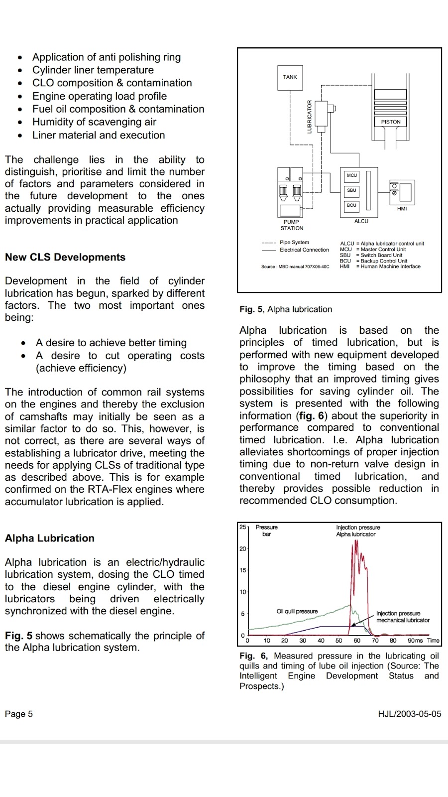
- Alpha lubrication
- SIP Swirl injection principle lubrication


1. Alfa lubricator feed regulations
Depends on the speed and load on the engine & Sulphur content in fuel.
The lubr concept is intermittent type- a relatively large amount of oil is injected for every 4 or 5 revolutions.
2. Alpha lubricator full(Bhowmick)
3. Cylinder lubrication..what if solenoid valve fails?(Sarkar)
2. Alpha lubricator full(Bhowmick)
3. Cylinder lubrication..what if solenoid valve fails?(Sarkar)
If a solenoid vv malfunctions, the l.o setting resets to maximum
SAFETY FEATURES
If lubricator malfunctions, gives a alarm and slowdown for one lubricator fitted in 260-600mm bore
In 700-980, other lubricator receives twice the supply.
4. alpha lubricator principle and details(Sarkar)
4. alpha lubricator principle and details(Sarkar)
based on injecting specific volume of cyl oil at precised timing.
5. RTA SULZER, cyl.lubtrication as per load variation,how,diagram(BND) LCD(Load index signal in B&W) lubricators ..y frequency control motors are used?.purpose?----lode change dependent(BND)
6. detailed working of alpha lubricators. How amount of oil supplied is controlled n changed with load/ sulpher content changes(Mitra)(injuction frequency only)
7. why lubrication is more in two stroke thn four stroke engine(Sarkar)
specific lub oil consumption. Calculations(Decider Rao) 5. RTA SULZER, cyl.lubtrication as per load variation,how,diagram(BND) LCD(Load index signal in B&W) lubricators ..y frequency control motors are used?.purpose?----lode change dependent(BND)
6. detailed working of alpha lubricators. How amount of oil supplied is controlled n changed with load/ sulpher content changes(Mitra)(injuction frequency only)
7. why lubrication is more in two stroke thn four stroke engine(Sarkar)
8. Main Engine cylinder liners what type of lubrication is there Condition under which hydrodynamic and boundary take place (Chakravarty)()
at sea u have exhausted with cyl oil..what will u do..next port is 5 days ahead.(…..)desile And A/E LO high feed rate
ALPHA LUBRICATION SYSTEM
The new lubricating system is based on the principle of injecting a specific volume of oil into the cylinder, via a number of injectors, for every four (or every five, six, etc.) revolutions. Furthermore, the precise timing ensures that all cylinder oil is delivered directly onto the piston ring pack where it is needed. This can be seen in Fig. 2, which shows the pressure measured in the oil injector during a cycle with lube oil injection as well as during a cycle without lube oil injection. The passage of the four piston rings is clearly seen in the pressure signal for the cycle without lube oil injection, and the precision of the new lubricator is obvious.


The lubricator itself, Fig. 3, has a small piston for each lubricator quill in the cylinder liner and the power for injecting the oil comes from the sys pressure, supllied by the pump station at 45bar acting on a larger common driving piston. Thus, the driving side is a conventional common rail system, whereas the injection side is a high-pressure positive displacement system, thus giving equal amounts of lube oil to each quill and the best possible safety margin against clogging of single lube oil quills.

For the larger bore engines, each cylinder has two lubricators (each serving half of the lube oil quills) and an accumulator, while the small bore engines (with fewer lube oil quills per cylinder) are served by one lubricator per cylinder. The pump station includes two pumps (one operating, the other on stand-by with automatic start up), a filter and coolers.
The lubricator can be delivered for our conventional engines in which case it is controlled by a separate computer unit comprising a main computer, controlling the normal operation, a switchover unit and a (simple) back-up unit.
The amount of oil injected can be adjusted automatically or manually as required, e.g. at load changes, start/stop, at reduced engine load (different modes are available), sulphur % in the fuel, temperature level on liner surface, variation in cylinder oil BN, etc
The cylinder control unit calculates the injection frequency depending on the fuel index and tacho signal. Injection function is controlled by sending an ON-OFF signal to the solenoid vv at the correct timing which is determined by the angle encoder(which gives TDC position fitted at fore end of the c/shaft)
It gives a signal to the solenoid valve of the lubricator to set the piston stroke, injecting high lo press to the quills.An inductive sensor gives pistion position feedback. After a predetermined time interval based on the rpm, the CCU transmits an OFF signal to the solenoid vv which shuts off the sys pr and opens the return oil sys.
The safety features of this system are as follows:
In the event of malfunctioning solenoid valve or transducer, the oil dosage will automatically be increased to the maximum volume. If the oil pressure falls, the computer will start stand-by pump, close down the faulty pump and sets on the alarm. In this system if one lubricator malfunctions (980-700 mm bore engines), the oil dosage from the other lubricator will be automatically doubled, and an alarm will be given whereas for 600-260 mm bore engines, alarm and slow down ensue.
An inductive sensor in each lubricator monitors the movement of the lubricator piston a signal is sent to the control computer system which has a backup for safety.
Alpha ACC (Adaptive Cylinder oil Control)
The principle of the Alpha ACC
The basic feed rate control should be adjusted in relation to the actual fuel quality and amount being burnt at any given time. The sulphur percentage is a good indicator in relation to wear, and an oil dosage proportional to the sulphur level will give the best overall cylinder condition.
The following two criteria determine the control:
- The cylinder oil dosage shall be proportional to the sulphur percentage in the fuel
The cylinder oil dosage shall be proportional to the engine load (i.e. the amount of fuel entering the cylinders) What is Pulse Lubrication System?
A pulse lubrication system is an electronically controlled cylinder oil lubrication system for Wartsila engines, wherein metered quantity of cylinder oil is injected in to the liner, depending on the engine load. This ensures that accurate amount of cylinder oil is delivered inside the liner at the correct set-time for that particular engine load.
Construction and Working of Pulse Lubrication System

There are normally eight quills attached to the cylinder liner in a single row, which gets the oil supply from the electronically controlled dosage pump.
The oil is supplied to the dosage pump from daily tank via fine filter of 40 microns.
The quills consist of a duct passage to store metered quantity of oil. The area of this duct passage and the quantity of oil can be altered by changing the position of the central piston.
There are crank angle sensors attached to the engine which give signals to the control unit in order to inject oil at the correct position of piston movement.
200 bar high pressure servo oil reduced to 50 bars are supplied to the lubricator unit, which pressurises the centre piston in the quills. This injects oil inside the liner at adequate pressure for even distribution.
WECS (Wartsila Engine Control System) which is the master controller of the Pulse lubrication system controls the solenoid valve opening and the oil injection
Each unit is provided with 8 lubricating quills, 2 piping systems of Cylinder oil and servo oil, and A 4/2 solenoid valve to servo oil flow.
After receiving signal from the crank angle sensor, at the correct position i.e. between the pack of piston rings, WECS allows the solenoid valve to open and pass the servo oil. This in turn presses the central piston and delivers the oil stored in the duct passage of the quills.
As soon as the injection is over, there is a small orifice which fills the duct passage again with the cylinder oil as the central piston moves backward. This ensures that the oil is always present in the chamber in metered quantity as decided by the WECS after calculating load and sulphur content of the fuel.
Benefits of Pulse Lubrication System
Reduction in Cylinder oil Feed rate –up to 0.7 gm/kwh and thus reduction in operating cost
Well précised delivery of metered cylinder oil giving better lubrication to piston ring and liner
Better distribution of oil within the line
Less fouling of combustion space
Less fouling of scavenge spaceReduction in Cylinder oil Feed rate –up to 0.7 gm/kwh and thus reduction in operating cost
Well précised delivery of metered cylinder oil giving better lubrication to piston ring and liner
Better distribution of oil within the line
Less fouling of combustion space

best article on cyl lubrication
ReplyDeleteI want to post a remark that "The substance of your post is amazing" Great work. Gate valves are primarily used to permit or prevent the flow of liquids. It is because of their ability to cut through liquids, that they are commonly used in this industry. With an increase in the global energy demand, the demand for the equipment used in the oil and gas industry is also on a rise. So here we have the list of Top Global Gate Valve Manufacturers. gate valve manufacturers
ReplyDeleteGreat article—very clear and informative. I especially liked the way you explained the key points in a practical way. Thanks for sharing such useful insights! LUBRICANT BLENDER
ReplyDelete
ReplyDeleteGreat article on the oil lubrication system! It clearly explains how continuous and controlled oil flow is essential for reducing friction and maintaining machine efficiency. A well-designed lubrication system not only improves performance but also extends equipment life and minimizes maintenance costs. Very insightful and useful for industrial applications.
Really valuable content. Thanks for sharing LUBRICANT BLENDER
ReplyDeleteGreat information about the oil lubrication system. A reliable oil lubrication solution plays a vital role in maintaining smooth machine operation, reducing friction, and preventing component wear. It helps industries improve equipment efficiency, minimize maintenance needs, and extend the lifespan of machinery. Choosing the right lubrication system ensures better performance and consistent productivity in industrial applications.
ReplyDelete